- 0xdurakiIBUS Overview
The IBus (from Infotainment Bus) is rather simple protocol (controller network), since only one (1x) wire is used for communication, unlike CANBus which consists of two (2x) wires: Rx & Tx that enables Infotainment Systems to exchange data with each other. Another example why IBus is simple protocol is due to device components (hardware system) likely includes the software (sic. firmware) support for it, and such busline can further hook up on LIN bus transceiver.
IBus by nature requires an UART, and a single IBus frame contains 32 bytes:
- First part is protocol length
- Second part is actual command code (data)
That means the factual limit of 32 bytes is imaginary, as we can extend protocol length and append command data. The last two (2) bytes of IBus frame are used for checksum crc validation. This gives us 14 channels that are controlled by a single IBus (length=32bytes).
Therefore, if we want to send command to 4 channels, we would use 8 bytes data. Then we would add two crc bytes acting as checksum validation, which would end in 12 bytes frame. To send these frames, we would use 115200 baud rate with data a la:
0x0C // length 12 bytes
0x40 // command code
0x00 //cha 1 low byte
0x00 //cha 1 high byte
0x00 //cha 2 low byte
<…>
0x4C //checksum low
0x00 //checksum high

Bus Communication Speeds
Data must be transmitted at high speed in order to make digital communication practical. The speed of these signal is referred to as the data rate (formerly baud rate). Depending on the type of bus network used, data can be transmitted from 9600 bits per second (9.6k/bps) to 500K bits per second (500K/bps).
Below is a list of different busline types and their bauds:
|Model|Bus Type|Data Rate|Structure| |E38|I/K/P Bus|9600|Linear| |E38|CAN|500000|Linear| |E38|D-Bus|9600|Linear| |E65|K-CAN-S|100000|Linear| |E65|K-CAN-P|100000|Linear| |E65|PT-CAN|500000|Linear| |E65|MOST|22500|Ring| |E65|byteflight|1000|Star| |E65|Sub-Busses|9600|Linear|
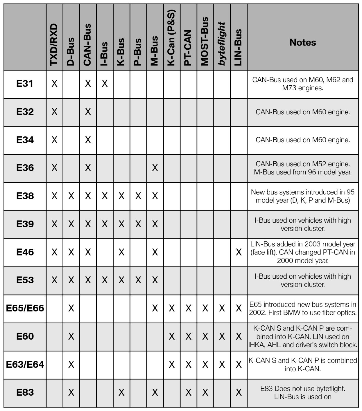
Below is a listing by model of the major bus networks in use. Please refer to image below to get disclosure of different busses implemented through the years and models.
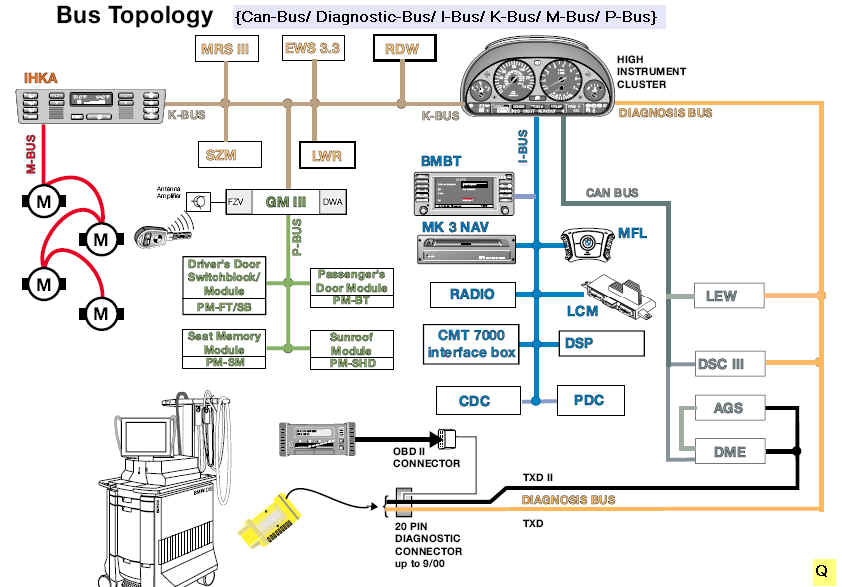
 Common Automotive Busline Topology
To identify IBus, its almost always white wire, with a red stripe and/or yellow dots.
It’s important to note that LINBus, as well as KBus, IBus and KLine (ISO9141) are all essentially the same. The only difference in their busline is electrical noise that each tries to solve via different specs. All of these serial communication protocols work by having the signal wire gently pulled up to +12V by one device on the bus. Device transmit by pulling the line to Ground (GND). Each device on the busline receives the same signal by monitoring the level on the wire.
They differ by the resistor used to pull the signal, and a few technical parameters. The pull-up resistor is anywhere between ~510Ohm-1kOhm, and the slew rate (how quickly you slam wire to ground) varies. The pull-up might be implemented with a current source, and good transmitter taper - anytime the drive level of the signal gets near 0V, as to round the edges.
The speed and protocol also differs, but in short, that is all digital circuity and firmware running on these protocols. Common microcontrollers (MCU) support all of the after mentioned protocols, with only slight changes in configurations.
The IBus are designed to withstands shorts to ground, and/or to +12V, but be careful to not short system components. If the IBus is correctly isolated (as it should be), the overvoltage and undervoltage protection should be put in place during manufacturing process. Therefore, we can say IBus is quite robust and solid.
IBus System Components
- Instrument Clusters
- In-dash Navigation Display
- Navigation Computer
- Radio/RDS Module
- Radio CD Changer
- Multi-function Steering Wheel Buttons
- LCM aka Light Control Module
- Telephone Control Module
- Parking Distance Control
- Windows, Doors, and other non-sensitive components
 Common Automotive Busline Topology
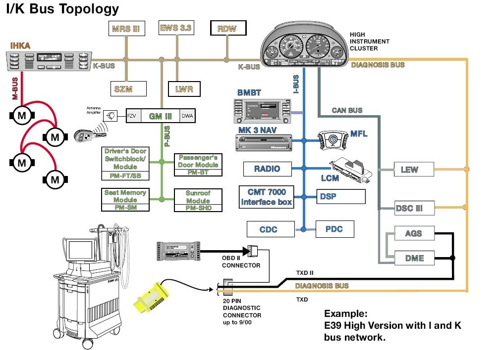
 Another example of I/K-Bus Topology
IBus (in) Radio CD Changer
The IBus connector that is in typical old BMW CD Changer system component contains three (3x) wires - brown, red w/ green stripes and white w/ yellow bands. These 3x wires on Radio CD Changer are as following: Ground (GND), the Power (+12V) and presumably the third one is IBus signal wire.
Since IBus is a digital signal (remember pulling-up from +12V-0V?), one can use a multimeter - specifically, voltmeter and ohmmeter to confirm that the IBus is not shorted to ground. Once confirmed, you can then measure the voltage of that busline. The voltage should vary at around ~ +8V.
IBus (in) Speed/RPM
The vehicle speed and RPM message is sent from the instrument cluster IKE module to all devices (global, GLO). It represents the current vehicle speed in kmph and the current engine RPM.
Defined Message Format
|Message Code|0x18| |Message Length|7 bytes| |Data Size|2 bytes| |Frequency|every 2 sec.|
The DB1 and DB2 directives below declare internal designations:
|DB1|DB2| |Speed|RPM|
Where:
Speedis actual speed inkmph * 2. To calculate speed, multiply DB1 with 2 (SPEED=DB1*2).RPMis actualRPM / 100. To calculate RPM, multiply DB2 with 100 (RPM=DB2*100)
Therefore, when an IKE sends speed and RPM information globally (GLO) to other system components, the frame is as following:
0x80 0x05 0xBF 0x18 0x1A 0x0E 0x22
Which translates to IKE => GLO : Speed|RPM: SPEED 52 km/h 1400 RPM via the following frame specification:
|Meaning|IKE|LEN|GLO|TYPE|SPEED|RPM|CS| |Value|0x80|0x0F|0xBF|0x18|0x1A|0x0E|0x22|
Speed = DB1 = 0x1A (26 dec) x 2 = 52 kmph
RPM = DB2 = 0x0E (14 dec) x 100 = 1400 RPM
IBus (in) IKE
IKE is an abbrevation for the german term “Instrument-Kombi-Electronik” which means Instrument Cluster (Electronics). It displays the speed indicator, odometer, mileage, fuel level, state of the doors, lights, and service intervals (SI). More details about Instrument Clusters are in separate note. Details about protocol framing can be researched here.
Defined IKE Code Messages
|Code|Meaning| |0x11|Ignition status message| |0x17|Odometer Status (total km)| |0x18|Speed Message, KM/H and RPM| |0x19|Temperature Sensor Value|
0x11 Ignition Status
Single data byte. DB1 is bit mapped as follows:
7... ...0
xxxx xxx1 = KL_R
xxxx xx1x = KL_15
xxxx x1xx = KL_50
All other bits are unused. If no bits are set, ignition is off. Therefore, an example where IKE informs about the ignition state ‘ACC_1’ via GLO is:
|TX|LL|RX|MM|BYTE 0|CS| |0x80|0x04|0xBF|0x11|0x01|0x2B|
Diagnostics
Diagnose via Multimeter: Use a Multimeter to check for shorts in the ground against the IBus busline using Ohmmeter. If busline, or the components are not shorted, you may use Voltmeter to check for ~ +8V IBus signal.
Diagnose via NavCoder: The NavCoder is a computer software application allowing you to connect to the vehicle IBus, therefore acting as a MiTM (Man in the Middle) proxy interceptor, allowing you to sniff and analyze IBus message traffic. This would aloud general problems on IBus components, and what most likely is not a problem.
References
- arduino-ibustrx an Arduino library for BMW IBus busline communication
- Arduino BMW IBus Serial Interface for MCP2025
- Arduino IBus Library in C++
- BMW E46 IBus Documentation (GDrive)
- HackTheIBus Message Details