- 0xdurakiRFID (Reader) Interface
The “Serial RFID Card Reader” is an interface module commonly used to read UEM41000 RFID Card information with two output formats: UART, and Wiegand. The reader has a high sensitivity with maximum sensing distance of ~7cm. The specific RFID reader interface shown below has 4x pins based on Electronic Brick Interface, making it easy to be used on Arduino.
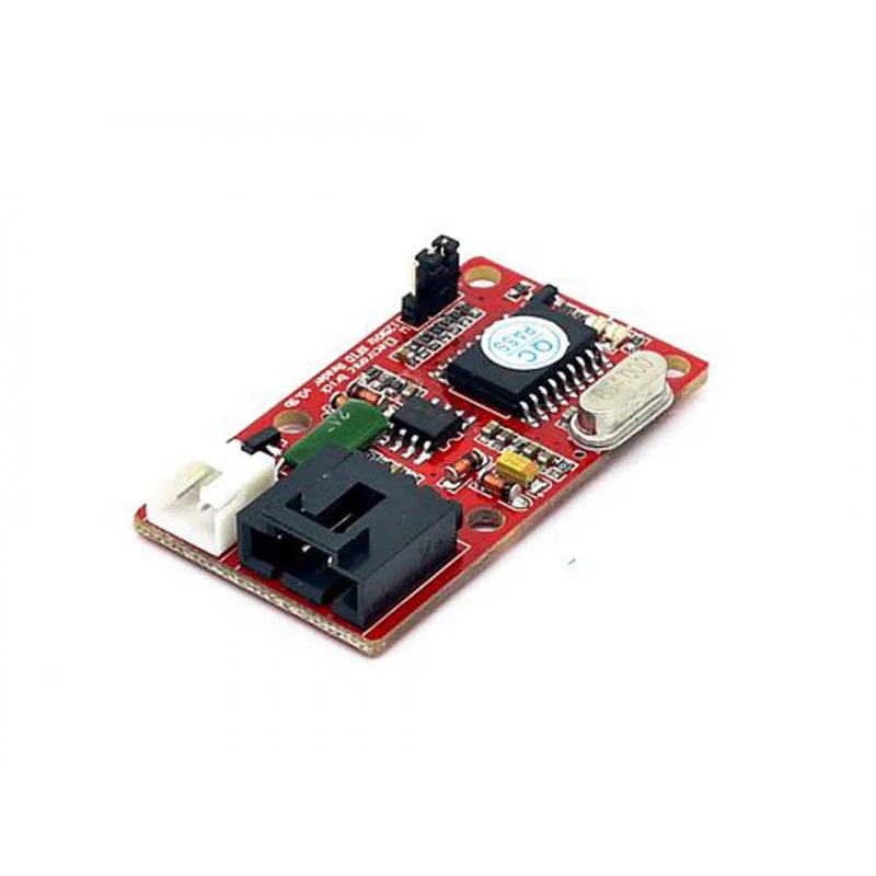 EB - 125Khz RFID Card Reader Interface
The RFID Reader is used to read the RFID tags/cards - commonly used to identify persons on electronic door locks, or in similar systems. The user identifies itself on the system (tag/card reader) by placing the card near the reader, and the system unlocks the door if the card is valid.
Connecting Serial RFID Reader to PC via USB
The instructions below provides information how to connect aftermentioned Serial RFID Card Reader to a PC using USB, which the interface module does not provide natively. This tutorial is based on USB-TTL Converter and is extendended from the base UART Interface notes of the Hardware Hacking section; since the RFID Reader will be connected via Serial TX/RX connection. Reference to RS232 Serial Interface notes for more details on a two-wire serial communication protocol & connectivity.
The USB-TTL Module is used to connect the RFID Reader to PC. Connect the RFID Reader to USB-TTL converter as shown in visual representation below.
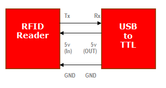 Connecting RFID Reader w/ USB-TTL Converter
The connection is rather simple, the TX from RFID goes to RX on USB-TTL module, and the RX from RFID is connected to TX on USB-TTL module. Both devices needs to have a common ground connection (GND). Now connect the RFID antenna to the RFID Reader module and this should complete the assembly process.
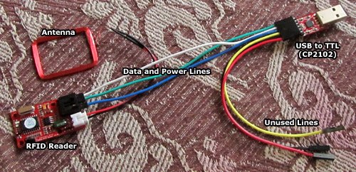 RFID via USB-TTL Setup
On the RFID Reader module, place the jumper towards “U” side, indicating correct data mode to be used in the interface setup.
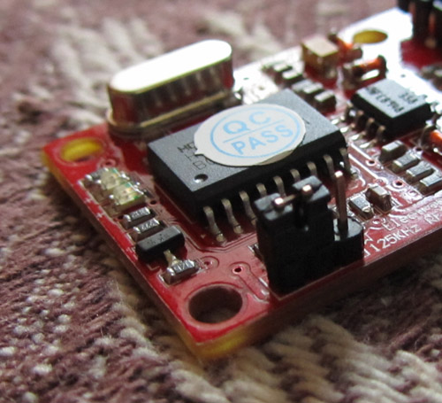 RFID via USB-TTL Setup
Connect the USB-TTL convertor to USB port on the PC, and start the “RealTerm Terminal Emulator” software, which is used to send/receive text data over serial ports.
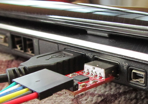 RFID via USB-TTL Setup
Inside the RealTerm, go to “Port” tab and set the following settings:
- Baud: 9600 (Baudrate/Bitrate)
- Port: Set to port number assigned to the CP2102 module (use “Device Manager” to identify correct port)
- Partiy: None
- Data bits: 8
- Stop bits: 1
- Hardware Flow Control: None
Interpreting RFID Data Packets
The RFID Data Packet is made up to 14 bytes. The first byte is a start byte whose ASCII value is decimal 2. This is labeled in RealTerm as STX. Next, there are 10 ASCII characters which indicates the ID of a tag/card in hexadecimal format. After that, there is a two byte checksum data, also represented in a hexadecimal format. Finally, there is an end byte whose ASCII value in decimal format is 3 - labeled in RealTerm as ETX symbol.
For example, if the tag/card data is 3D006217D7, the checksum would be caluclated as the following:
CHECKSUM = (3D) XOR (00) XOR (62) XOR (17) XOR (D7)
Use the calculator with scientific mode (WinNT: Calculator ~> View ~> Scientific) to calculate the above checksum.
Example calculation from above would result in value 9F, which is a presented in RealTerm as a checksum value. To convert the tag/card data 3D006217D7 to decimal value, remove the first two digits/bytes of the tag/card data, and take the rest 8 digits.
For example, if the tag/card data is 3D006217D7, removing the first two digits/bytes of it would result in 006217D7. Using the calculator in hex/scientific mode, enter the this value (006217D7) and change the calculator to Decimal mode (by clicking “DEC” button). Calculator will convert the hexadecimal byte data to decimal number. The resulting decimal value (in this case 6529631) indicates the tag/card number, sometimes shown on the tag/card itself, as show below:
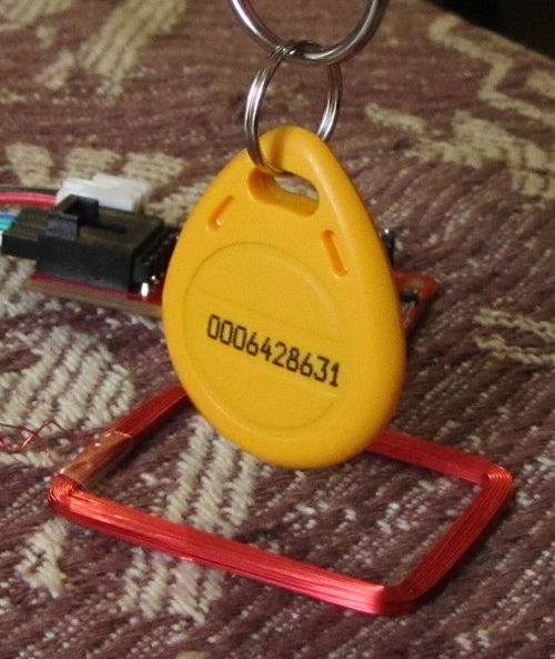 RFID Tag/Card ID