- 0xdurakiE34 Pinout Diagram
Note: if you can’t make sense of the “Terminal #” keywords in the pinouts below, refer to Terminal Designations, and DIN 72552 pages. In short, it represents a standardised/defined/constant Pin I/O.
E34 Radio Pinouts
The BMW Series 5 E34 Radio Pinouts are located here.
E34 Low Cluster - EURO - MY. 88-90 Pinouts
Details:
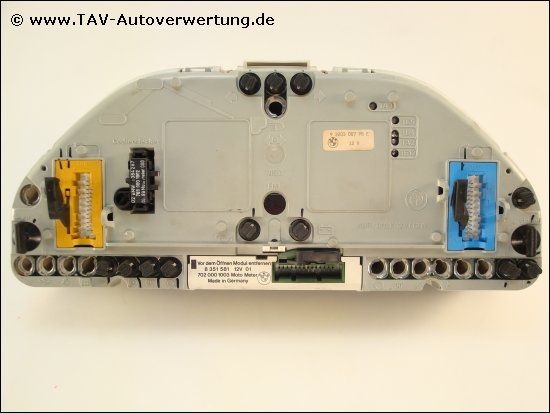
Cluster: Low (without Check Control - aka CCM)
Installed in: 518i M40 (import), 520i M20, 520i M50, 524td
Period: until 09/1990
Manufacturer: Motometer

Identification Features:
- Mechanical km counter in the speedometer
- Uneven scaling on the fuel gauge
- White back of the instrument cluster
- Coding plug (black) is in the back of the station wagon

Defects and remedies:
Replace the batteries on the circuit board (1.2V mignon). If these have leaked, they have usually already etched the circuit board - the only solution here is to replace them.
 Pinouts for the particular model (X16/Yellow, X13060/Blue)
Download full pinout diagram, showing Connection, Signal Type, and Pin#NO (for High Cluster). Requires MacOS and Numbers.app. Otherwise, here you can download a compiled pdf version.
Click for Pinouts Diagram
| Pin | Type | Description |
|---|---|---|
| Pin 1 | A | TxD Diagnostic Line |
| Pin 2 | E | ABS Indicator Lamp |
| Pin 3 | A | Brake Fluid Level |
| Pin 4 | E | Coolant Temperature Sensor |
| Pin 5 | A | Oil Pressure Signal |
| Pin 6 | NOT_USED | |
| Pin 7 | E | Preheating, Diesel |
| Pin 8 | SIA (Service Light) Reset | |
| Pin 9 | Charge Indicator Lamp, Terminal 61 | |
| Pin 10 | E | Start Clear Diesel |
| Pin 11 | NOT_USED | |
| Pin 12 | E | RxD Diagnosis Line |
| Pin 13 | E | NOT_USED |
| Pin 14 | A | Airbag Lamp Indicator |
| Pin 15 | A | Ignition Lock |
| Pin 16 | A | Fuse, Terminal 15, Ignition |
| Pin 17 | A | Terminal R for Airbag Indicator Lamp |
| Pin 18 | A | Ground Connection |
| Pin 19 | NOT_USED | |
| Pin 20 | A | TI (DME Control Unit) Signal |
| Pin 21 | E | Fuse, Terminal 30 |
| Pin 22 | E | Fuse, Terminal R, Accessories Wire (ACC) |
| Pin 23 | A | Main Beam Indicator Lamp |
| Pin 24 | A | Turn Signal Indicator Lamp |
| Pin 25 | A | Fuse, Terminal 15, Ignition |
| Pin 26 | E | TD Signal |
E34 Pinout Diagram